Setting up a Cross Reference Table
This chapter shows how to create and use a cross reference table in QIE. Traditionally interface engines only allow cross reference tables to have two columns. Column A which contains the original value and Column B which contains the new mapped value. However, unique to QIE is the ability to have multiple columns in a cross reference table. This capability reduces the number of cross reference tables needed and increases the accuracy of the table mappings. For example physicians can have multiple Ids like a National Provider Identifier (NPI), Prescribing Physician ID or State License number, Drug Enforcement Administration number (DEA), and many other internal numbers. With QIE's multi column capability you can manage all of the provider's numbers in one table and cross reference each number as needed across multiple interfaces.
Creating a Cross Reference Table
Step 1: Create a New Table under System Variables
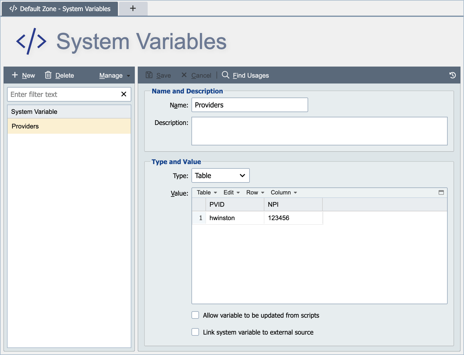
Navigate to the System Variables on the left hand side navigation menu and then on the content page click on New to create a new table.
Name the table 'Providers' and then select from the type drop down menu Table. Then tab off the type field to enter the first value in the table. By default QIE creates a table template with only two columns. You can click on the Column menu to add additional columns as needed.
Next put your cursor in any value within column 1 and select Column from the menu and choose Rename Column and call column 1 PVID. Repeat these steps and rename column 2 to NPI.
Note
In addition to creating the table in QIE you can also from the Table menu import or export a csv file wherein you can manage the table in Microsoft Excel.
Step 2: Insert a New Mapping Function
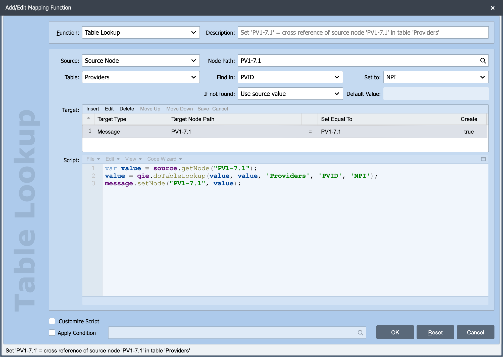
Click on the blue Mapping node in the Visual Channel Editor and then click Insert to insert a new mapping.
From the function drop down menu select Table Lookup. Then set the following values: Source = Source Node, Node Path = PV1-7.1, Table = Providers, Find in = PVID, Set to = NPI, If not found = Use source value.
The last step is to add the table mapping result back into the message. To do this select Insert from the Target menu and then set Message as the Target Type and PV1-7.1 as the Target Node Path.
Step 3: Test the Mapping
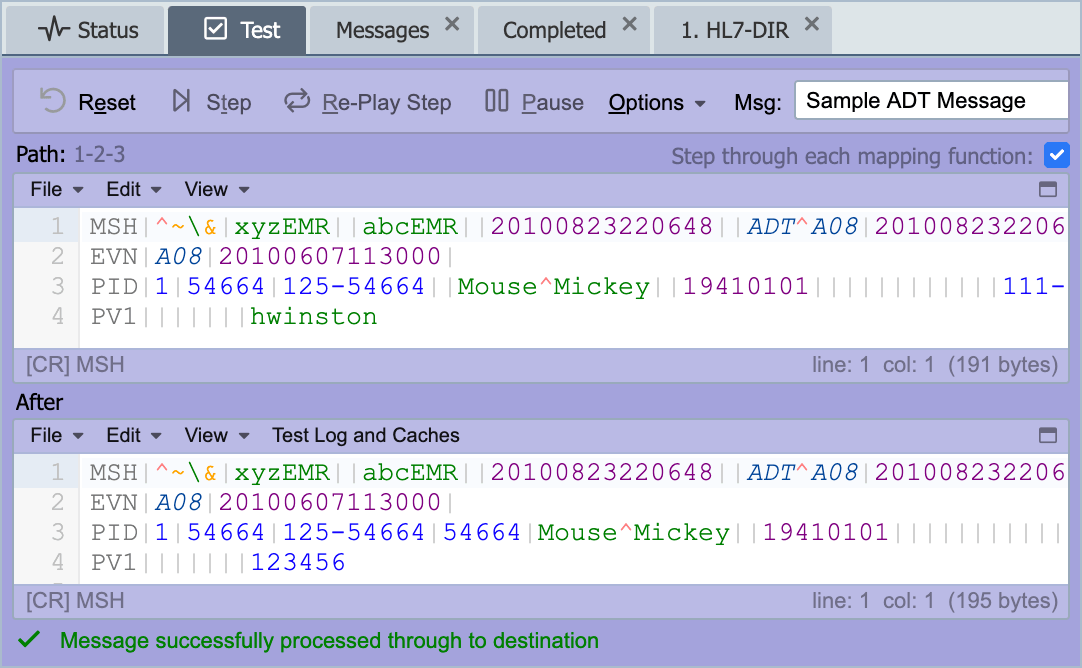
Select the test tab to test the mapping. Be sure to make a test with a value that you know is not in the table to test the Not Found Behavior.
Before testing this mapping function click on the Source Node and select the Sample Messages and click on edit to edit the ADT sample message. Now add the following PV1 segment to the sample messages (PV1|||||||hwinston|).